Arduino Servo Code Myths Debunked: A Professional Guide for 2026

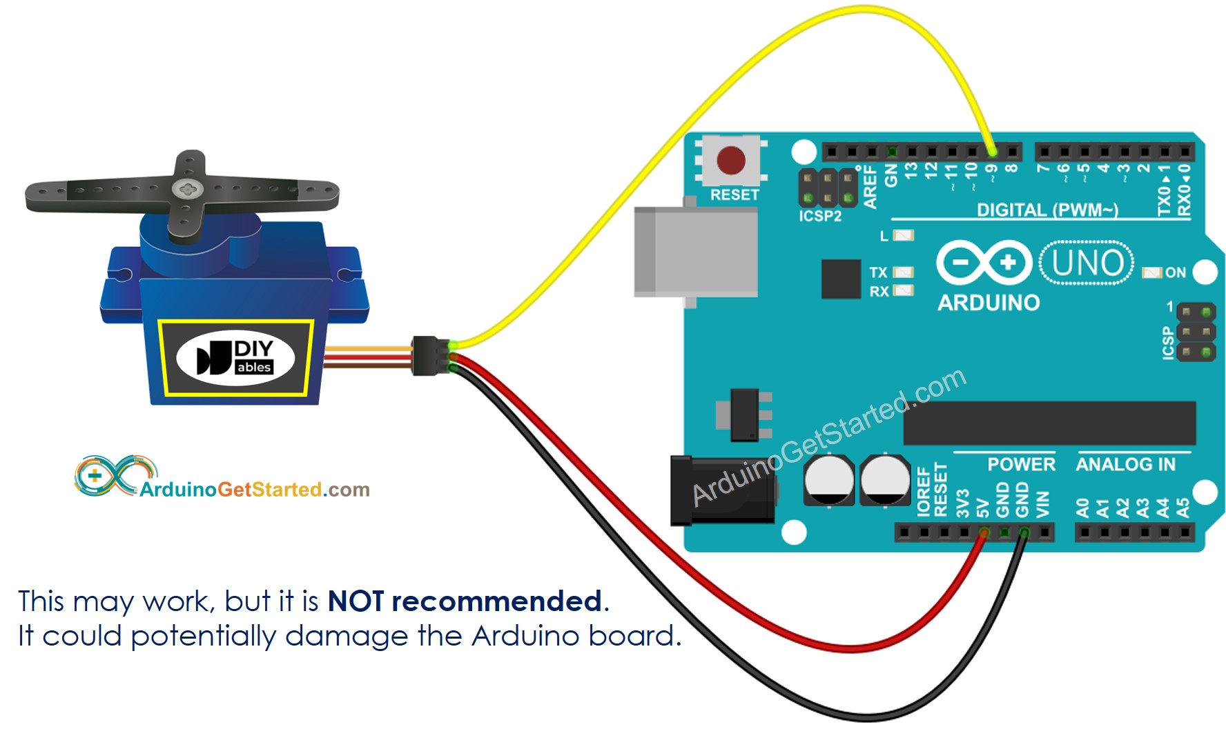
To optimize Arduino servo performance, you must move beyond the "beginner" tutorials that often propagate technical inaccuracies. The most common myths involve the reliability of the delay() function, the assumption that all servos rotate exactly 180 degrees, and the dangerous practice of powering servos directly from the Arduino’s 5V pin.
Successful servo integration requires understanding the relationship between pulse-width modulation (PWM) signals, hardware timers, and mechanical physical limits. By debunking these common misconceptions, developers can build more responsive, stable, and durable robotic systems.
The Reality of Servo Control Logic
In the Arduino ecosystem, the Servo library is the standard tool for controlling hobbyist motors. However, the simplicity of the library often masks the complex interaction between software instructions and hardware execution. As we move further into 2026, the complexity of projects—ranging from automated home systems to advanced drone gimbal stabilization—demands a deeper understanding of what happens when you call servo.write().
A servo is not a simple "plug-and-play" component that mirrors code perfectly. It is a closed-loop system consisting of a motor, a potentiometer for feedback, and a control circuit. When the Arduino sends a signal, it is not sending a "position"; it is sending a pulse of a specific duration. The servo’s internal electronics interpret this pulse and attempt to move the output shaft to a matching orientation. Most myths arise from a failure to account for the physical and electrical "lag" or "offset" that exists between the code and the physical world.
Myth 1: You Can Safely Power Servos from the Arduino 5V Pin
This is perhaps the most persistent and damaging myth in the maker community. While it may work for a single, small SG90 servo under no load, it is a recipe for system instability.
The Problem with Current Draw
The onboard voltage regulator of an Arduino (such as the Uno or Nano) is designed to power the microcontroller and a few low-power sensors. A standard hobby servo can pull between 100mA and 250mA while moving, but its stall current—the current it draws when it starts moving or encounters resistance—can spike to over 1 Amp.
When the servo draws more current than the Arduino’s regulator can provide, the voltage drops. This often causes the Arduino to undergo a "brownout" reset. If you see your code restarting every time the motor moves, this is why.
The Correct Approach in 2026
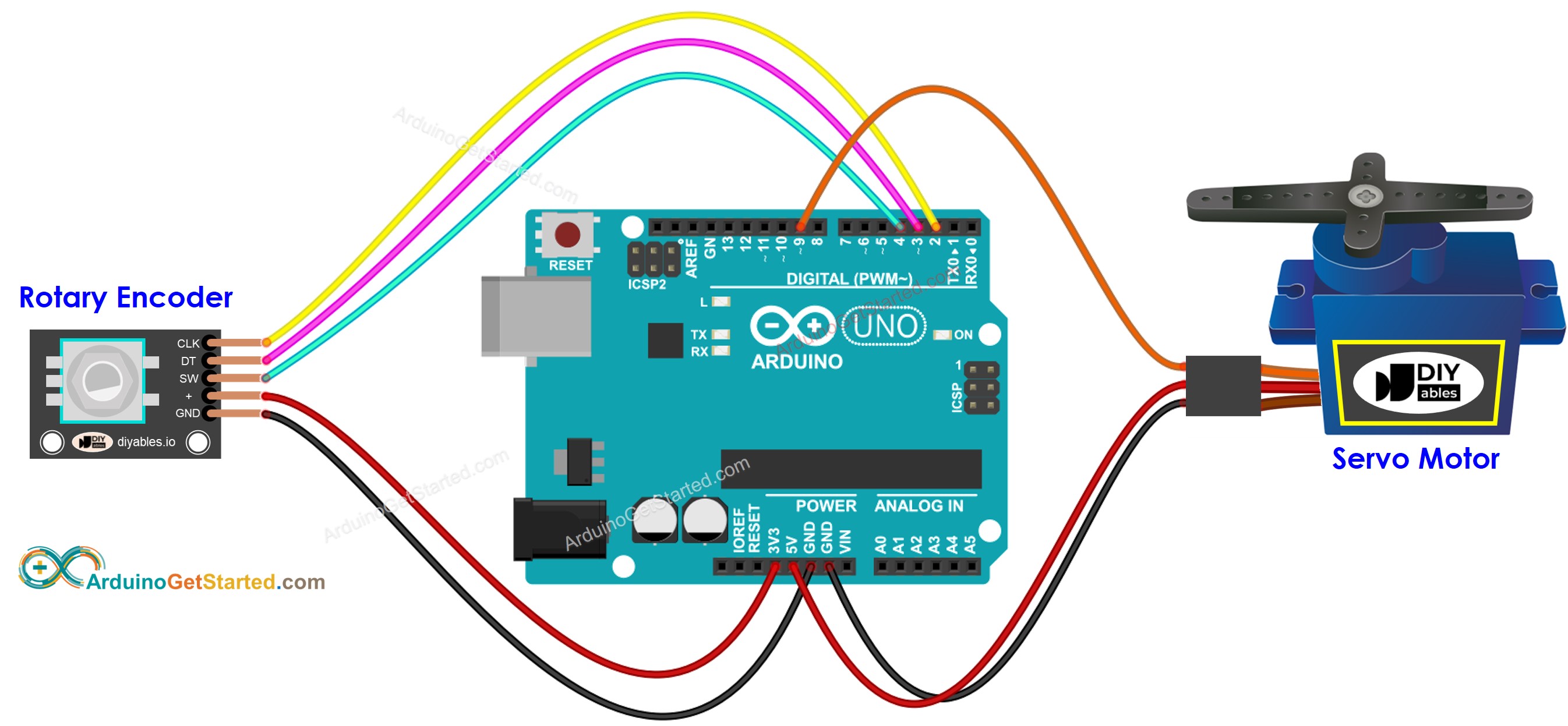
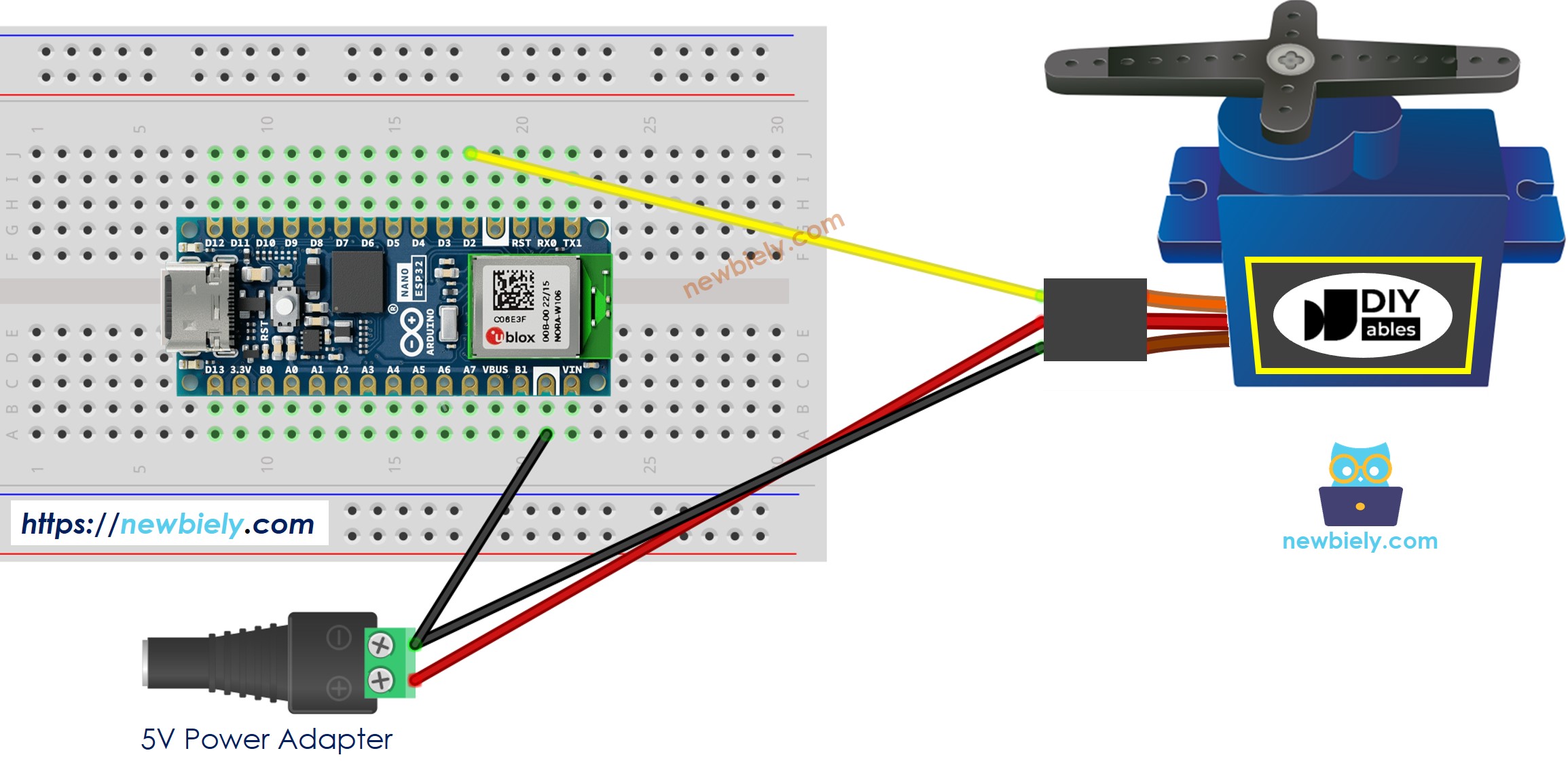
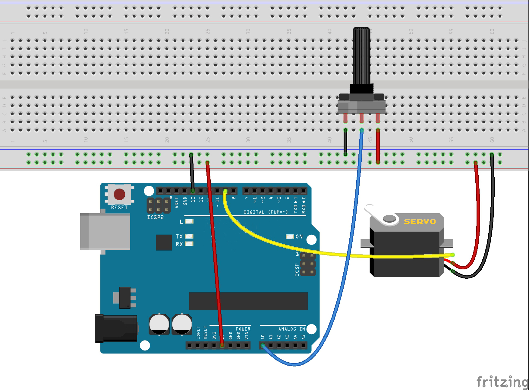
Always use an external power source for servos. This could be a 4-cell NiMH pack, a dedicated 5V/6V power supply, or a buck converter connected to a LiPo battery. Crucially, you must connect the ground (GND) of the external power supply to the Arduino’s GND. Without a common ground, the control signal has no reference point and the servo will behave erratically or not move at all.
Myth 2: The delay() Function is the Best Way to Manage Timing
Early tutorials frequently use delay(15) after a servo.write() command to give the motor time to move. While functional for a "Blink" sketch, this is catastrophic for complex projects.
The "Blocking" Problem
The delay() function is a "blocking" command. It stops the processor entirely for the specified duration. If your project needs to read a sensor, update an LCD, or listen for a button press while the servo is moving, it cannot do so if the code is stuck in a delay().
The Non-Blocking Alternative
In 2026, professional Arduino code utilizes millis() for timing. This allows for "multi-tasking" by checking if enough time has passed to move the servo to the next increment without pausing the entire program. This is often referred to as a State Machine approach. By using non-blocking code, you can control ten servos independently while simultaneously processing complex sensor data.
Myth 3: All Standard Servos Have a 0 to 180 Degree Range
Many beginners write code that assumes every servo can reach exactly 0° and 180°. In reality, hobby servos are mechanical devices with significant manufacturing tolerances.
Physical vs. Software Limits
Most "180-degree" servos actually have a physical range closer to 160 or 170 degrees. Forcing a servo to write(0) or write(180) when it cannot physically reach that point causes the motor to strain against its internal plastic stops. This leads to:
- High current draw and overheating.
- Audible "buzzing" or "jittering."
- Stripped internal gears.
Calibration is Mandatory
To debunk this myth in your own project, you must find the true limits of your specific motor. Start at 90 degrees and slowly move toward the ends until you hear the motor begin to strain. Note those values and use the map() function or constrain() in your code to ensure your software never requests a position the hardware cannot achieve.
Myth 4: servo.write(angle) is More Accurate Than Microseconds
The standard servo.write(angle) command accepts a value from 0 to 180. While convenient, it is actually a simplified abstraction.
The Power of writeMicroseconds()
Internally, the Arduino Servo library converts your angle into a pulse width measured in microseconds (µs). Standard servos usually respond to pulses between 1000µs (0°) and 2000µs (180°). However, many modern digital servos respond to a wider range, such as 500µs to 2500µs.
Using servo.writeMicroseconds() provides much finer control. Instead of only 181 possible positions (0-180), you have 1000 or more increments. This is essential for precision robotics or camera stabilizers where a 1-degree jump is too coarse.
Myth 5: PWM Pins are Required for All Servos
A common misconception is that servos must be connected to the specific pins marked with a tilde (~) on the Arduino board (the hardware PWM pins).
Software PWM vs. Hardware PWM
The Arduino Servo.h library does not actually use the hardware PWM functionality of those specific pins (which is used by analogWrite()). Instead, it uses timer-based interrupts to generate the 50Hz signal on almost any digital pin.
On an Arduino Uno, you can technically run servos on any of the digital pins (D0-D13) and even the analog pins (A0-A5). However, be aware that using the Servo library often disables analogWrite() functionality on specific pins (typically pins 9 and 10 on the Uno) because they share the same internal hardware timer (Timer 1).
Myth 6: Continuous Rotation Servos Can Be Controlled by Angle
"Continuous rotation" servos are often marketed alongside standard servos, leading to the myth that you can command them to "stop at 45 degrees."
Speed and Direction, Not Position
Once a servo is modified for continuous rotation, the internal feedback loop (the potentiometer) is disconnected or replaced. The servo.write() command no longer represents an angle. Instead:
write(90)usually represents "Stop."write(180)represents "Full speed forward."write(0)represents "Full speed backward."
You cannot tell a continuous rotation servo to move to a specific orientation because it no longer knows where its shaft is. To achieve positional control with such a motor, you would need an external encoder.
Comparison of Servo Control Methods
| Feature | servo.write(angle) |
servo.writeMicroseconds(us) |
Custom PWM (Manual) |
|---|---|---|---|
| Resolution | Low (181 steps) | High (1000+ steps) | Highest (Processor dependent) |
| Ease of Use | High (Intuitive) | Medium | Low (Requires timer knowledge) |
| Compatibility | Standard Hobby Servos | High-end/Digital Servos | Industrial Actuators |
| Range Mapping | Fixed (0-180) | Flexible (Custom limits) | Fully Custom |
| Best For | Basic prototypes | Precision Robotics | Non-standard frequencies |
Advanced Troubleshooting: Eliminating "Jitter"
Even with perfect code, many users experience "jitter"—small, erratic movements of the servo arm. This is rarely a "bug" in the code and almost always a hardware or environmental issue.
- Inadequate Power: If the voltage ripples when the motor moves, the control circuit gets confused. Add a large electrolytic capacitor (470µF or 1000µF) across the power and ground rails of your servo breadboard to act as a buffer.
- Signal Interference: Long wires between the Arduino and the servo can act as antennas, picking up electromagnetic interference (EMI). Keep signal wires as short as possible or use twisted pair wiring.
- Timer Conflicts: If you are using other libraries (like
NewPingfor ultrasonic sensors or certain IR remote libraries), they may be fighting over the same hardware timer. This causes the pulse width to fluctuate slightly, leading to jitter. In 2026, using boards with more timers, such as the Arduino GIGA R1 or ESP32, can mitigate these conflicts. - Cheap Potentiometers: In low-cost servos, the internal feedback potentiometer may have "dead zones" or electrical noise. If a single servo jitters while others on the same circuit are stable, the hardware itself is likely faulty.
Optimal Code Structure for 2026
To avoid the pitfalls of these myths, adopt a professional coding structure. The following conceptual approach ensures your servo logic is robust:
- Initialization: Define min/max pulse widths in the
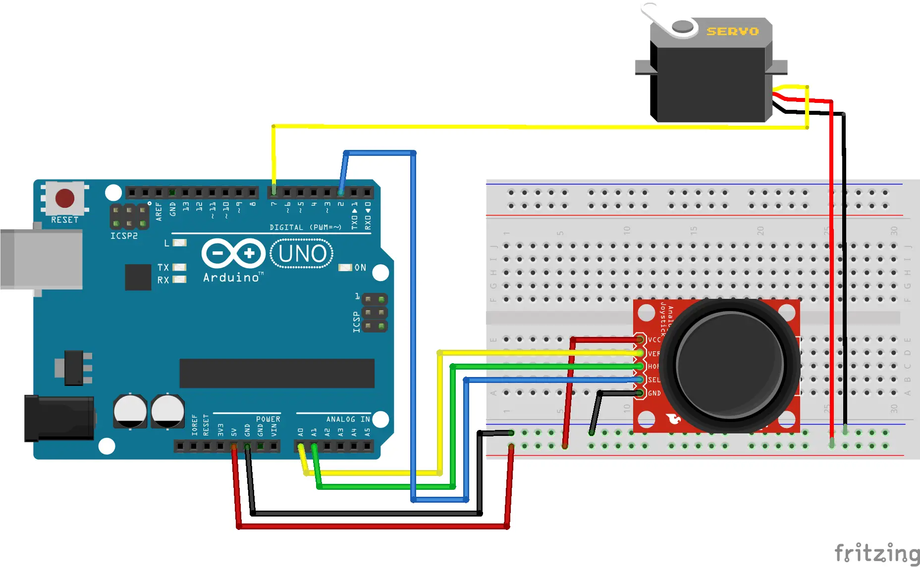
attach()function. For example:myServo.attach(pin, 500, 2500);. - Input Smoothing: If the servo position is based on a sensor (like a joystick), use a running average or a low-pass filter to smooth the input values before sending them to the servo.
- Incremental Movement: Instead of jumping from 0 to 180, use a loop or a non-blocking timer to increment the position by 1 degree every few milliseconds. This reduces the mechanical "jerk" and extends the life of the gears.
- Detaching: If the servo does not need to hold a position under load, use
servo.detach()to stop sending the signal. This can stop the "buzzing" noise and save power, though the arm will be free to move if pushed.
FAQs
Why does my servo move to 90 degrees as soon as I turn on the Arduino?
When you call myServo.attach(pin), the library defaults to a "neutral" position (usually 90 degrees or 1500µs) if no other position has been specified. To prevent this, call myServo.write(desired_start_angle) immediately before the attach() command in your setup() function. This ensures the first signal the servo receives is your intended starting position.
Can I use the Servo library with an ESP32 or ESP8266?
Yes, but the implementation is different. While the standard Servo.h is for AVR-based boards (like the Uno), the ESP32 uses ESP32Servo.h. The underlying principles of PWM and external power remain the same, though the ESP32 offers significantly more hardware timers, allowing for smoother control of many more servos simultaneously.
How many servos can I control with one Arduino?
On a standard Arduino Uno, the library supports up to 12 servos. On the Arduino Mega, this increases to 48. However, the limitation is rarely the number of pins; it is almost always the power supply. Providing enough current for 12 servos to move simultaneously requires a significant power management strategy, likely involving a dedicated PCA9685 PWM driver board.
What is the difference between an analog and a digital servo in terms of code?
From the perspective of your Arduino code, there is no difference. Both use the same 50Hz PWM signal. The difference is internal: a digital servo has a higher-frequency internal microprocessor that checks the position more often, resulting in better holding torque, faster response, and higher precision.
Why is my servo getting hot even when it isn't moving?
This usually means the servo is "stalling." You have likely commanded it to an angle it cannot physically reach (see Myth 3), and it is constantly trying to move against a physical stop. Alternatively, the servo may be supporting a heavy load that exceeds its "holding torque," causing the motor to draw constant current to maintain its position.
Next Steps for Developers
To master servo control, transition your projects away from delay() and toward a state-machine architecture. Experiment with writeMicroseconds() to see the increase in precision, and always calculate your project's maximum current draw to select an appropriate external power supply. For those moving into complex robotics, exploring dedicated 16-channel PWM drivers like the PCA9685 will offload the timing requirements from your Arduino, leading to smoother motion and more processing overhead for your main application logic.
Image Gallery
Select an image to open it in a new tab.


Celine Dubois
Contemporary Living and Global Arts Columnist
