Learning how to solder a resistor is a foundational skill in electronics, bridging theoretical circuit design and physical construction. Achieving a reliable, electrically conductive, and mechanically sound solder joint requires understanding temperature regulation, chemical flux properties, metallurgy, and proper preparation techniques. Whether you are assembling a printed circuit board (PCB) or repairing vintage audio equipment, mastering this process ensures long-term circuit stability and prevents intermittent failures.
Understanding Soldering Fundamentals and Safety
Before heating any metallic components, it is critical to understand the tools, safety measures, and chemical processes involved in soldering. A solder joint is not merely a glue holding wires together; it is an alloy bond formed by the interdiffusion of base metals and molten filler metal.
Safety Protocols and Workspace Preparation
Soldering involves working with temperatures ranging from 300°C to 400°C (572°F to 752°F). Proper safety gear and a well-ventilated workspace are non-negotiable prerequisites.
- Ventilation: Rosin-core solders release flux fumes that can irritate the respiratory system and trigger asthma. Always use a dedicated fume extractor or work in a well-ventilated area with a cross-breeze.
- Eye Protection: Splatter from molten solder or clipped component leads can cause severe eye injury. Safety glasses are mandatory.
- Thermal Safety: Always assume a soldering iron is hot. Never leave a plugged-in iron unattended, and store it securely in a weighted stand with a protective cage.
- Personal Hygiene: Wash your hands thoroughly with soap and water after handling lead-based solder alloys.
The Role of Flux and Alloy Composition
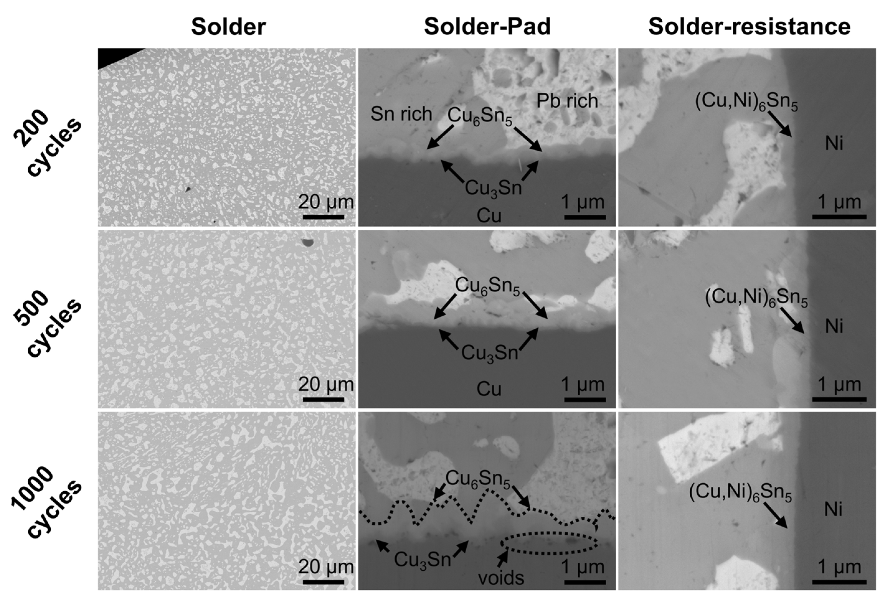
Traditional electronics solder is an alloy of tin and lead (typically 60/40 or 63/37 eutectic), while modern commercial electronics utilize lead-free alternatives such as SAC305 (96.5% tin, 3.0% silver, 0.5% copper). Lead-free solder requires higher melting temperatures (around 370°C vs. 315°C for leaded solder) and lacks the mirror-like shine of leaded joints when cooled, often appearing slightly matte or grainy.
Embedded within the core of the solder wire is chemical flux. Flux is a cleaning agent that removes microscopic surface oxides from the metals being joined, prevents new oxidation during the heating process, and reduces surface tension so the molten solder can flow evenly into the joint.
Tools and Materials Required
Precision electronics work requires specialized equipment. Attempting to solder a delicate resistor with a heavy-duty plumbing iron will invariably damage the component or lift the copper traces off the PCB.
| Tool / Material | Specification / Recommendation | Purpose |
|---|---|---|
| Soldering Station | Temperature-controlled, 50W–75W | Provides stable, adjustable thermal output for consistent heating. |
| Solder Wire | Rosin-core (63/37 leaded or SAC305 lead-free) | Acts as the conductive filler metal containing cleaning flux. |
| Solder Tip Cleaner | Brass sponge or damp cellulose sponge | Removes burnt flux and oxidation from the iron tip. |
| Flush Cutters | Precision diagonal cutters | Trims excess component lead wire after soldering. |
| Tweezers / Hemostats | ESD-safe fine-tipped tweezers | Holds the resistor in place and acts as a temporary heat sink. |
| Isopropyl Alcohol (99%) | High-purity solvent with a nylon brush | Removes residual corrosive flux after soldering is complete. |

Step-by-Step Procedure: How to Solder a Resistor
Executing a clean solder joint follows a strict, repeatable sequence. Rushing any phase can result in cold joints, bridging, or thermal damage to the resistor.
Step 1: Preparation and Component Inspection
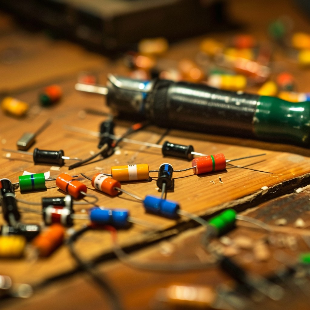
Inspect the resistor value using its color bands or a digital multimeter to ensure it matches your schematic requirements. Clean the PCB pads using isopropyl alcohol and a clean cloth or fiberglass pen if there is any oil, dust, or oxidation present.
Step 2: Bending and Inserting the Leads
Resistors are supplied with straight axial leads. To fit them into through-hole PCB footprints:
- Hold the resistor body and bend the leads at a clean 90-degree angle right where they exit the ceramic or carbon body. Space the bends to match the hole spacing on the circuit board.
- Insert the leads through the top (silkscreen side) of the PCB. Push the resistor body down until it rests flush against the board, unless thermal management guidelines require a small air gap underneath.
- On the underside (copper trace side) of the board, bend the leads outward at a 45-degree angle. This mechanical lock prevents the resistor from falling out when you flip the board over.
Step 3: Tinning the Soldering Iron Tip
Turn on your soldering station and set the temperature (approximately 350°C for leaded solder or 385°C for lead-free). Once heated, wipe the tip quickly across the brass sponge to remove old oxidation. Apply a tiny amount of fresh solder to the tip. This process, known as "tinning," improves thermal transfer between the iron and the joint.
Step 4: Heating the Joint
Never apply solder directly to the soldering iron tip and let it drip onto the board. Instead:
- Place the flat face of the soldering iron tip so that it makes simultaneous contact with both the protruding resistor lead and the annular copper pad on the PCB.
- Hold the iron steady in this position for 2 to 3 seconds to bring both metals up to the melting temperature of the solder.
Step 5: Feeding the Solder
While maintaining contact with the iron tip against both the lead and the pad, touch the end of the solder wire to the opposite side of the joint (where the lead meets the pad).
- The solder should melt instantly upon contact with the heated metals, flowing smoothly around the lead and covering the pad.
- Feed a small amount of solder—just enough to form a concave, volcano-like shape. Remove the solder wire first, then remove the soldering iron. Total contact time should rarely exceed 4 to 5 seconds per joint.
Step 6: Cooling and Inspection
Allow the joint to cool completely without disturbance. Do not blow on the joint, as rapid cooling can create micro-fractures in the crystalline structure of the metal. Once cooled, inspect the joint under a magnifying glass or jeweler's loupe. A proper joint features a bright, shiny finish (for leaded solder), a concave meniscus profile completely wetting both the lead and the pad, and no excess blobs or spikes.
Post-Soldering Clean-Up and Trimming
Once all joints are verified, two essential final tasks remain:
- Lead Trimming: Using precision flush cutters, snip off the excess wire length just above the top of the solder joint. Cut flush against the angled side of the cutters for a clean snip. Always point the clipped lead downward or shield it with your thumb so the wire snippet does not fly across the room.
- Flux Removal: Residual rosin flux is slightly acidic and can attract moisture from the air over time, potentially causing corrosion. Dip a nylon-bristled brush into 99% isopropyl alcohol and scrub the solder side of the board gently to dissolve the flux residue, then dry it immediately with a lint-free wipe.
Troubleshooting Common Soldering Defects
Even experienced technicians occasionally encounter imperfect joints. Recognizing these defects allows for prompt correction before powering up a circuit.
Cold Solder Joints
- Symptom: The joint appears dull, frosty, granular, or rounded into a ball that fails to spread across the pad.
- Cause: The component moved while the solder was cooling, or insufficient heat was applied to the pad.
- Solution: Reapply the soldering iron tip to reheat the joint until the solder reflows smoothly. Add a tiny drop of external flux if necessary, and hold the component completely still until it solidifies.
Solder Bridges
- Symptom: Excess solder connects two adjacent pads or traces that should remain isolated.
- Cause: Too much solder applied, or an iron tip that is too wide for fine-pitch layouts.
- Solution: Clean the soldering iron tip completely, touch it to the bridge to liquefy the excess solder, and draw the iron away while dragging the excess solder up onto the tip. Alternatively, use clean copper desoldering braid (wick) with flux to absorb the excess metal.
Insufficient Solder (Starvation)
- Symptom: The joint looks thin, exposes bare copper on the pad, or does not fully encompass the resistor lead.
- Cause: Removing the solder wire too quickly or failing to heat the pad adequately.
- Solution: Reheat the joint and feed a small additional amount of solder wire until the proper concave fillet forms.
Frequently Asked Questions
Can I overheat a resistor while soldering?
Yes. Although resistors are manufactured to withstand normal assembly temperatures, holding a high-heat iron against a lead for longer than 6 to 8 seconds can thermally degrade the internal resistive element, shifting its resistance value permanently or cracking its ceramic housing. Always use the correct temperature and work efficiently.
What is the difference between leaded and lead-free solder for beginners?
Leaded solder (63/37 alloy) has a lower melting point, flows more easily, and solidifies with a shiny, reliable surface finish, making it much more forgiving for beginners. Lead-free solder requires higher tip temperatures, has a narrower plastic melting range, and demands precise thermal technique to avoid cold joints, though it is legally required in commercial electronics manufacturing within many jurisdictions.
Do I need to clean flux off the circuit board?
Yes, especially if you are using rosin-based fluxes that leave a sticky, amber residue. While mildly corrosive-resistant when dry, this residue absorbs ambient moisture and dust over time, which can introduce parasitic leakage currents in sensitive analog or high-frequency digital circuits.
How do I know if my soldering iron tip is ruined?
A healthy soldering iron tip is coated in iron plating and takes solder smoothly. If the tip turns black, refuses to accept solder (known as "tip starvation" or oxidation), or develops pits and holes where the copper core is exposed beneath the plating, it must be replaced or aggressively dressed with tip tinner and cleaning blocks.
What wattage should a soldering iron be for general electronics work?
A variable temperature-controlled soldering station ranging from 50 to 75 watts is ideal. It provides enough thermal reserve to heat larger ground planes while allowing precise temperature regulation down to 300°C for delicate components like surface-mount parts and standard resistors.
Image Gallery
Select an image to open it in a new tab.



Mateo Castillo
Decentralized Finance and E-Payments Strategist
