Understanding Vertex Coordinates in Geometry: A Comprehensive Guide
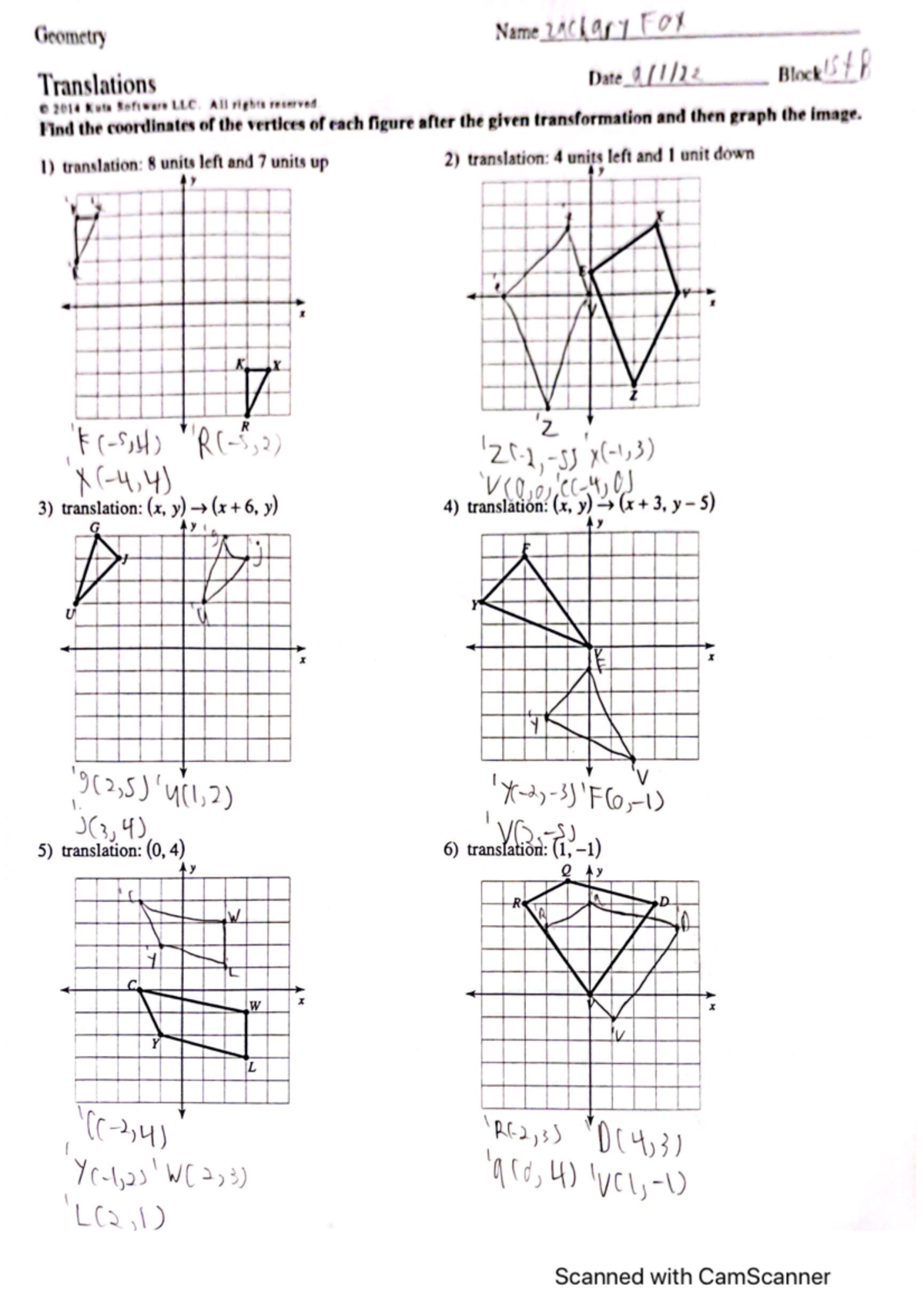
Vertex coordinates are numerical representations that define the exact location of a corner point—or vertex—of a geometric shape within a coordinate system. By assigning an ordered set of numbers (such as x, y, and z) to these points, mathematicians and designers can precisely map, calculate, and manipulate shapes in two-dimensional planes or three-dimensional space, serving as the foundational language for fields like engineering, computer graphics, and architecture.
The Role of Coordinate Systems in Geometry
To understand vertex coordinates, one must first understand the environment in which they exist: the coordinate system. The most common system used in geometry is the Cartesian coordinate system, named after the French mathematician René Descartes. This system functions like a grid, allowing us to pinpoint any location relative to a fixed origin point (0, 0) in two dimensions or (0, 0, 0) in three dimensions.
In a 2D Cartesian plane, a vertex is represented by an ordered pair (x, y). The "x" value indicates the horizontal distance from the vertical axis (y-axis), while the "y" value indicates the vertical distance from the horizontal axis (x-axis). When moving into three-dimensional space, a third coordinate, "z," is added to represent depth or height, resulting in an ordered triplet (x, y, z). These coordinates are the "addresses" of the vertices of a polygon or polyhedron. Without these specific numeric identifiers, it would be impossible to perform complex geometric operations, such as calculating the surface area, volume, or rotation of an object.
Anatomy of a Polygon: Vertices, Edges, and Faces
Geometry distinguishes between several components of shapes. Understanding these is essential for locating vertices accurately:
- Vertex (Plural: Vertices): A point where two or more edges meet. It is the fundamental building block for defining the shape's boundaries.
- Edge: A line segment that connects two vertices.
- Face: A flat surface of a 3D shape, bounded by edges and defined by the vertices that form its perimeter.
For example, consider a simple square on a 2D plane. If the bottom-left corner is at (0, 0) and the square has a side length of 2 units, the four vertices must be (0, 0), (2, 0), (2, 2), and (0, 2). By defining these four sets of vertex coordinates, we have fully described the position, orientation, and dimensions of the square. If you change a single coordinate—for instance, changing (2, 2) to (2, 3)—the shape is no longer a square; it becomes a trapezoid. This sensitivity to coordinate values is why vertex management is critical in precision-based disciplines.
Identifying Vertices in 2D vs. 3D Space
The complexity of working with vertex coordinates increases significantly when transitioning from 2D to 3D.
2D Geometry (The Plane)
In two dimensions, vertices are restricted to the x and y axes. This is the realm of traditional Euclidean geometry, used in drafting and blueprinting. When solving for vertex coordinates here, you typically use distance formulas or slope calculations to determine the exact placement of a point. If you know the distance from the origin and the angle, you can use trigonometry (sine and cosine functions) to convert polar coordinates into the Cartesian (x, y) coordinates required to plot the vertex.
3D Geometry (Space)
In three dimensions, the inclusion of the z-axis allows for the definition of complex polyhedra like cubes, pyramids, or spheres. In modern computer-aided design (CAD) software, objects are represented by "meshes"—a collection of thousands or millions of vertices connected by edges to form triangular or quadrilateral faces. Understanding the coordinates of these vertices allows software to perform real-time rendering, collision detection, and lighting calculations. If you are animating an object, the "motion" you see is actually the continuous, rapid recalculation of those vertex coordinates over time.
Practical Applications of Vertex Mapping
The utility of vertex coordinates extends far beyond the classroom. They are the backbone of various professional industries in 2026:
- Computer Graphics and Gaming: Every character or environment you see in a game is a mesh. The GPU (Graphics Processing Unit) of your computer or console is essentially a highly optimized calculator designed to process these vertex coordinates at extreme speeds to create fluid motion.
- Structural Engineering: When engineers design a bridge or a building, they map the structural nodes (vertices) using high-precision coordinate systems to ensure that loads are distributed correctly. If the coordinates are off by even a fraction of a millimeter, the physical structure may fail.
- Additive Manufacturing (3D Printing): Before a file can be printed, it must be converted into a format (like STL) that describes the surface of an object as a series of connected triangles. These triangles are defined entirely by their vertex coordinates. The printer reads these coordinates to know exactly where to deposit material.
Comparison of Coordinate Systems
While Cartesian coordinates are the most common, they are not the only way to express vertex location. Depending on the task, professionals might use different systems.
| System Type | Primary Use Case | Coordinate Representation |
|---|---|---|
| Cartesian | Standard geometry, CAD, 3D modeling | (x, y) or (x, y, z) |
| Polar | Circular motion, robotics, navigation | (r, θ) – radius and angle |
| Spherical | Geographic mapping, planetary science | (r, θ, φ) – radius, azimuth, zenith |
| Barycentric | Finite element analysis, triangle interpolation | (λ1, λ2, λ3) – relative to triangle vertices |
Common Mistakes and How to Avoid Them
Even for experienced professionals, errors in coordinate geometry can lead to significant problems. Here are the most frequent pitfalls:
- Axis Misalignment: A common mistake in 3D modeling is confusing the "up" axis. In some software packages, the Z-axis is "up," while in others, the Y-axis serves that purpose. Always verify your coordinate system orientation (the "handedness" of the coordinate system) before importing data.
- Coordinate Precision Loss: When working with very large or very small coordinates, floating-point errors can occur in computer software. This can lead to "jitter" or gaps in a mesh. To mitigate this, professionals often use "local" coordinate systems for individual objects rather than keeping everything in one global world-space coordinate system.
- Incorrect Vertex Ordering: When defining a face in 3D software, the order in which you list the vertices (e.g., clockwise vs. counter-clockwise) determines the "normal" of the face—or which way the surface is facing. If the vertices are defined in the wrong order, the shape may appear inside-out or fail to render shadows correctly.
Troubleshooting Coordinate Issues
If you find that your geometric model is not appearing as expected, follow these troubleshooting steps:
- Check the Origin: Ensure that your coordinates are relative to the intended origin (0, 0, 0). If you have accidentally moved your object to a massive coordinate value (e.g., at a distance of 1,000,000 units), your software may struggle with rendering precision.
- Verify Unit Scaling: Confirm whether your coordinate system is using millimeters, meters, or inches. A shape defined with vertices at (1, 1) will look entirely different if the unit scale is changed from meters to centimeters.
- Inspect Vertex Connectivity: Use an edge-view or wireframe mode in your software to ensure that vertices are actually connected. Sometimes, "dangling" vertices exist that are not part of a face, which can cause errors in geometric calculations or printing.
Frequently Asked Questions
How do I calculate the distance between two vertices? You use the distance formula derived from the Pythagorean theorem. For 2D points (x1, y1) and (x2, y2), the distance is the square root of [(x2 - x1)² + (y2 - y1)²]. For 3D points, you simply include the z-dimension: square root of [(x2 - x1)² + (y2 - y1)² + (z2 - z1)²].
What happens if I change a vertex coordinate? Changing a single coordinate shifts that specific point in space. Because vertices are connected by edges, moving one vertex will stretch or compress any polygons (faces) attached to it. This is the primary method for "deforming" objects in 3D animation software.
Are vertex coordinates always integers? No. In most professional applications, vertex coordinates are represented as floating-point numbers (decimals). This allows for the high level of precision required for realistic models and engineering components, as geometric shapes rarely align perfectly with whole-number grid intersections.
What is the difference between local and global coordinates? Global (or world) coordinates describe an object's position relative to the center of the entire environment. Local (or object) coordinates describe the position of vertices relative to the object's own center point, making it easier to rotate or scale the object without affecting its position in the world.
Can I convert between coordinate systems? Yes. Through a process called coordinate transformation, you can convert between Cartesian, polar, and other systems using specific mathematical matrices. Most software handles these conversions automatically when you switch viewing modes or export files.
Next Steps for Mastery
To improve your proficiency with vertex coordinates, focus on learning basic vector algebra. Vectors provide the mathematical framework to move, rotate, and scale collections of vertices efficiently. Practice creating simple geometric shapes in a 3D modeling tool like Blender or a CAD program like Fusion 360, and manually enter coordinates into the input fields rather than relying solely on mouse dragging. This practice will build your intuition for how coordinate values relate to physical shapes in space.
Image Gallery
Select an image to open it in a new tab.
Omar Farooq
EdTech Innovation and Virtual Pedagogy Journalist
