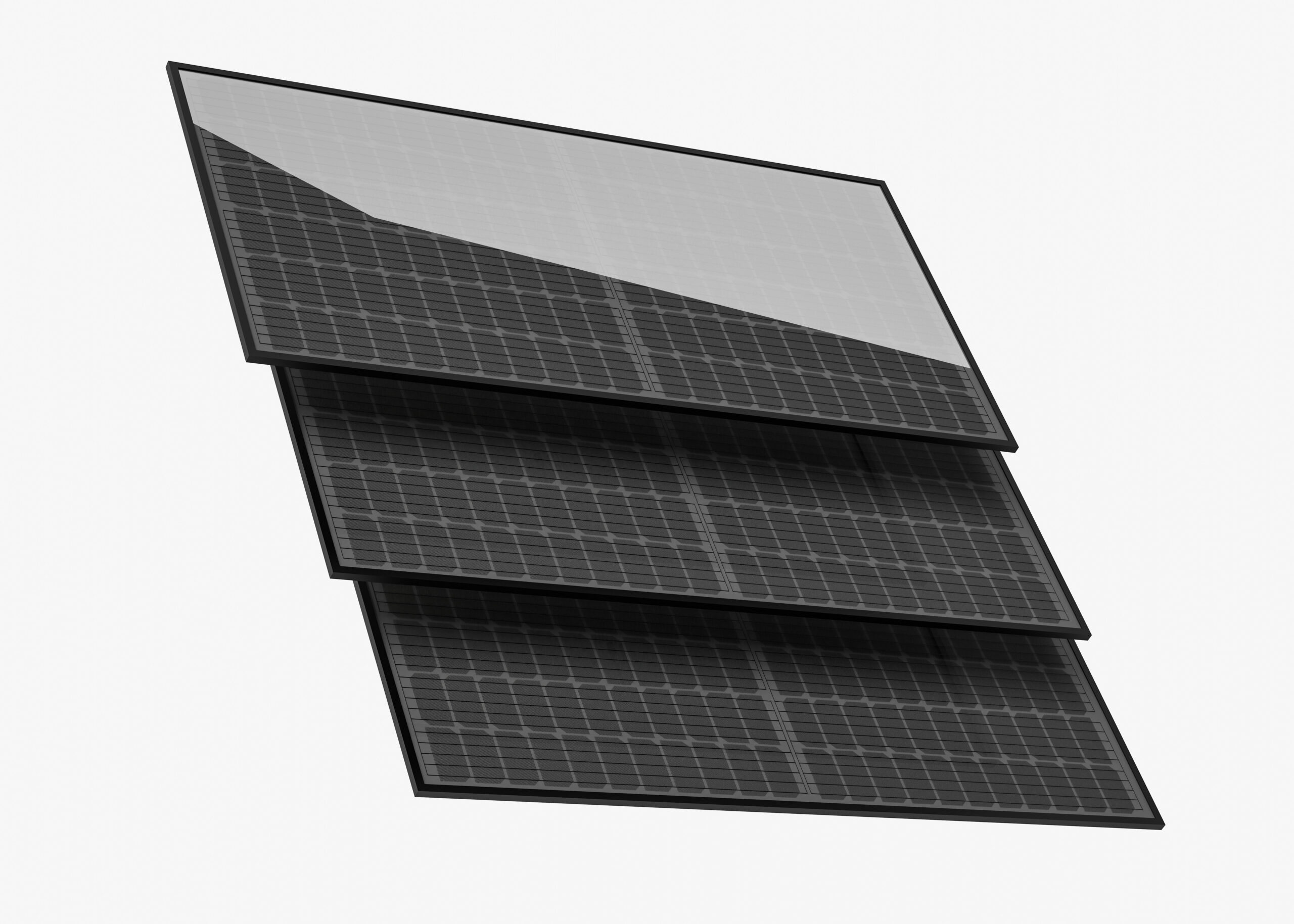
To connect solar cells into a functional solar panel, you must solder individual cells together in a series circuit using tabbing wire. This involves connecting the positive (back) of one cell to the negative (front) of the next. Multiple series strings are then joined in parallel using thicker bus wire to achieve the desired voltage and current output for your specific energy needs.
Building a solar panel from individual cells is a meticulous process that bridges the gap between basic electronics and renewable energy engineering. While commercial panels are widely available in 2026, the DIY approach remains a vital skill for off-grid enthusiasts, researchers, and hobbyists who require custom dimensions or specific voltage outputs that off-the-shelf products cannot provide. Understanding the physics of cell interconnection is the first step toward creating an efficient, durable energy source.
Understanding the Fundamentals of Solar Cell Connection
Before picking up a soldering iron, it is essential to understand how electricity behaves within a solar array. A single silicon solar cell—typically a 6x6 inch square—generates approximately 0.5 to 0.6 volts regardless of its size. The size of the cell determines the amperage (current), while the way you connect them determines the total voltage and power of the final panel.
Series Connections for Voltage
In a series connection, you connect the negative terminal of one cell to the positive terminal of the next. In the world of solar cells, the "front" (the side with the grid lines facing the sun) is the negative terminal, and the "back" (the silver-coated or spotted side) is the positive terminal. Connecting cells in series increases the total voltage while the current remains equal to that of a single cell. For example, connecting 36 cells in series (each providing 0.5V) results in an 18V panel, which is the standard requirement for charging a 12V lead-acid or lithium-iron-phosphate (LiFePO4) battery system.
Parallel Connections for Current
Parallel connections involve joining all the positive terminals together and all the negative terminals together. This configuration keeps the voltage the same as a single cell (or a single string) but adds the amperage together. In DIY panel construction, parallel connections are usually reserved for joining multiple "strings" of cells together at the end of the assembly process to increase the total wattage of the panel without exceeding the voltage limits of a charge controller.
Tools and Materials Required for Construction
Precision is the most critical factor in solar assembly. Because silicon cells are extremely fragile—often as thin as a human hair—having the correct tools prevents micro-cracks that can lead to "hot spots" and panel failure.
- Solar Cells: Polycrystalline or monocrystalline cells. Monocrystalline cells are more efficient but generally more expensive and slightly more brittle.
- Tabbing Wire: A thin, flat, pre-tinned copper ribbon used to connect the individual cells.
- Bus Wire: A thicker copper ribbon used to connect the ends of cell strings and carry the cumulative current to the junction box.
- Flux Pen: A tool used to apply liquid flux to the solder points. Flux is mandatory; without it, the solder will not bond to the silicon's silver contact points, leading to high resistance.
- Soldering Iron: A 40W to 60W iron is ideal. It must be hot enough to melt the solder quickly (to avoid heat-stressing the cell) but regulated to prevent burning the delicate materials.
- Encapsulant: Usually EVA (Ethylene Vinyl Acetate) film or a specialized solar-grade silicone to protect the cells from moisture.
- Backing Material: A rigid sheet, such as tempered glass or a high-durability polymer (TPT), to provide structural integrity.
- Junction Box and Diodes: A weather-resistant box to house the final wire connections and a blocking diode to prevent the battery from discharging back into the panel at night.
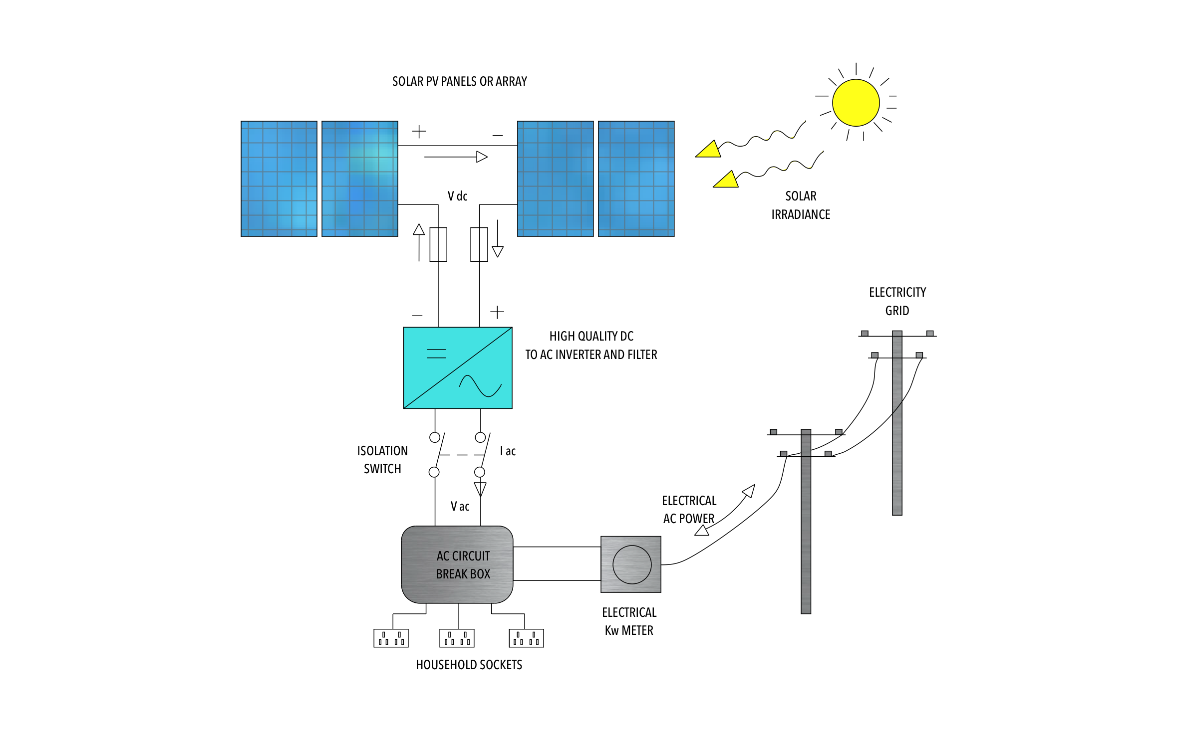
Step-by-Step Guide: Soldering and Stringing Solar Cells
The assembly process is divided into two main phases: tabbing the individual cells and stringing those cells together into rows.
Step 1: Tabbing the Cells
Start by measuring the length of the "busbars" (the thick silver lines running down the face of the cell). Cut your tabbing wire to slightly more than twice this length. This extra length is necessary because the wire must travel from the front of one cell to the back of the next.
Apply the flux pen along the entire length of the busbars on the front of the cell. Lay the tabbing wire over the busbar and run the soldering iron down the wire with gentle, even pressure. The heat will melt the pre-applied solder on the tabbing wire, bonding it to the cell. Repeat this for all busbars on the cell (usually two or three).
Step 2: Creating the String
Once you have several "tabbed" cells, it is time to connect them. Lay cell A face down. Place cell B face down next to it. Take the tabbing wires extending from the front of cell B and solder them to the silver contact pads on the back of cell A.
This creates a series connection: Front (Negative) of Cell B to Back (Positive) of Cell A. Continue this process until you have a "string" of cells that fits the dimensions of your panel frame. A common configuration is four strings of nine cells each for a total of 36 cells.
Step 3: Connecting Strings with Bus Wire
After completing your strings, lay them out on your backing material. The strings must be oriented so that the polarity alternates. For example, if String 1 ends with a positive lead at the top, String 2 should start with a negative lead at the top.
Use the thicker bus wire to bridge the gap between strings. Solder the bus wire across the ends of the strings to complete the circuit. This is where you determine the final output; for most DIY projects, you will connect all strings in series to maximize voltage.
Technical Specifications and Configuration Table
The following table outlines standard configurations for DIY solar panels using typical 6x6 inch (156mm) solar cells, assuming an average cell output of 0.5V and 8A (4 Watts).
| Configuration | Total Cells | Nominal Voltage | Max Current (Imp) | Total Wattage | Primary Application |
|---|---|---|---|---|---|
| 36 Cells in Series | 36 | 18V | 8A | 144W | 12V Battery Charging (Off-grid) |
| 60 Cells in Series | 60 | 30V | 8A | 240W | Grid-tie Inverters / 24V Systems |
| 72 Cells in Series | 72 | 36V | 8A | 288W | Large Scale / 48V Battery Banks |
| 36 Series x 2 Parallel | 72 | 18V | 16A | 288W | High-current 12V Systems |
Encapsulation and Weatherproofing
A common mistake in DIY solar construction is neglecting the environmental protection of the cells. Silicon and copper are highly susceptible to oxidation and moisture. Once your cells are soldered and tested, they must be sealed.
In 2026, the standard for DIYers is either a "glass sandwich" method or a "silicone pour." The glass sandwich involves placing the cell array between two sheets of tempered glass or a glass front and a TPT backsheet, with a layer of EVA film in between. This assembly is then heated (vacuum lamination) to melt the EVA, creating a permanent, airtight seal.
If vacuum lamination is not feasible, many builders use high-transparency, UV-stable liquid silicone. You build a small frame around the cells and pour the silicone over them. This method is easier for hobbyists but requires careful degassing to ensure no air bubbles are trapped, which could cause refraction losses or moisture pockets.
Testing and Quality Control
Before the final seal, you must verify the electrical integrity of your work. Testing should be performed at two stages:
- String Testing: Use a multimeter to check the DC voltage of each individual string under sunlight or a bright halogen lamp. If a string of 9 cells does not show roughly 4.5V, there is likely a "cold solder joint" (a connection that looks attached but does not conduct electricity) or a cracked cell.
- Open Circuit Voltage (Voc): Once the panel is fully wired but not yet connected to a load, measure the voltage across the final positive and negative leads. For a 36-cell panel, you should see between 20V and 22V in full sun.
- Short Circuit Current (Isc): Set your multimeter to Amps (ensure it can handle at least 10A) and measure the current directly. This confirms the panel is producing its rated power.
Common Challenges and Troubleshooting
Micro-Cracks
Silicon cells are extremely brittle. Pressing too hard with a soldering iron or flexing the string during assembly can cause micro-cracks. These are often invisible to the naked eye but will show up as "dead zones" in the cell, significantly reducing the panel's lifespan and efficiency. Always handle cells by the edges and use a specialized tabbing jig if possible to keep them flat.
High Resistance Joints
If your flux application is uneven, the solder may "bead" rather than flow. This creates high resistance, which generates heat. In a completed panel, these joints can become so hot they melt the encapsulant or cause the glass to shatter. This is known as a "hot spot." Ensure your solder joints are flat, shiny, and cover the entire width of the busbar.
Shading and Diodes
If one cell in a series string is shaded, it acts as a resistor to the entire string, bottlenecking the current and potentially overheating. To prevent this, install bypass diodes in the junction box. These allow current to "skip" a shaded string, preserving the output of the rest of the panel. Additionally, a blocking diode should be placed on the positive output wire to ensure that at night, the battery doesn't try to "light up" the solar panel, which would drain the battery.
Frequently Asked Questions
Can I mix different types of solar cells in one panel?
It is strongly discouraged to mix different types, sizes, or brands of cells. The panel's total current (amperage) is limited by the "weakest link" in the series. If you mix a 4A cell with an 8A cell, the entire panel will be restricted to 4A, wasting the potential of the higher-quality cells and causing heat buildup in the smaller cell.
What is the best way to clean cells before soldering?
Avoid using water or standard glass cleaners. If a cell has fingerprints or dust, use 99% isopropyl alcohol and a lint-free microfiber cloth. However, the best practice is to wear powder-free nitrile gloves during the entire assembly process to prevent oils from your skin from contaminating the silver contacts.
How long will a DIY solar panel last?
A professionally manufactured panel can last 25–30 years. A well-made DIY panel using EVA encapsulation and tempered glass can last 10–15 years. However, panels that are poorly sealed or use plexiglass (which yellows and warps over time) may fail within 2–3 years due to moisture ingress and UV degradation.
Is it cheaper to build a panel than to buy one in 2026?
Technically, no. Due to massive economies of scale in 2026, commercial panels are generally cheaper per watt than the cost of individual cells, tabbing wire, glass, and frames. The primary reasons to build your own are for education, custom-sized applications (like a specific curvature for a vehicle), or repair of existing arrays.
Do I need a charge controller for my DIY panel?
Yes. A solar panel's voltage fluctuates constantly based on sun intensity. Connecting a panel directly to a battery can lead to overcharging and permanent damage. Always use a Pulse Width Modulation (PWM) or Maximum Power Point Tracking (MPPT) charge controller between your panel and the battery bank.
Final Recommendation
For those embarking on their first solar panel build, start with a small 10-watt or 20-watt project before attempting a full-sized 100-watt+ array. This allows you to perfect your soldering technique and understand the thermal expansion of the materials without a significant financial risk. Once you have successfully built a small, weather-sealed unit that passes a multimeter test, you can scale up to larger configurations with the confidence that your connections are secure and your encapsulation is air-tight.
Image Gallery
Select an image to open it in a new tab.



Declan O'Connor
Higher Education and Campus Culture Reporter
